At Mentalab, we know that exceptional neuroscience data doesn’t just depend on advanced hardware, it starts with meticulous preparation. The International 10-20 System is the gold standard for electrode placement. Based on the original work by Jasper (1958), this system uses skull landmarks to ensure electrode positions correspond accurately to underlying cerebral cortex regions, allowing for reproducible and scientifically rigorous data across participants, studies, and recording devices.
Here is your visual, step-by-step guide to following the 10-20 system based on our latest protocols.
Step 1: Precision Head Measurement
The entire 10-20 system relies on proportional distances (10% and 20%) between specific anatomical landmarks. To find the right cap size, use a flexible tape measure to find the total circumference of the subject’s head, passing directly over the nasion (the bridge of the nose) and the inion (the prominent bony bump at the back of the skull). You can ask the participant to help by holding one end of the measurement tape over their nasion.
Selecting the correct cap size prevents the fabric from stretching unevenly, which would shift electrode positions away from their intended cortical targets and potentially discomfort the participant. Round your measured head circumference to the closest cap size.
For more information on what cap sizes are suitable for your participants, consult here: https://wiki.mentalab.com/user-guide/cap-size-guide/
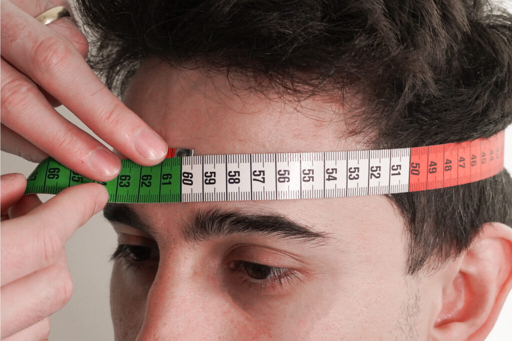
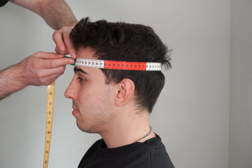
Figure 1a: Measuring the precise frontal baseline circumference right above the brow line.
Figure 1b: Overview of the horizontal tape path to ensure accurate skull circumference calculation.
Step 2: Aligning the Sagittal and Coronal Arcs
Once the correct cap size is chosen, place the cap on the participant’s head. You must align the central electrode strip along the sagittal plane (from nasion to inion). Ensure that the Cz (Vertex) marker sits exactly at 50% of the distance between the nasion and inion, and 50% of the distance between the left and right preauricular points. Preauricular points are the small anatomical depressions located immediately in front of each ear canal. Finally, ensure that the cap is not off-center diagonally, by ensuring the Fp1 and Fp2 positions in the front of the cap are equally distanced from each eye.
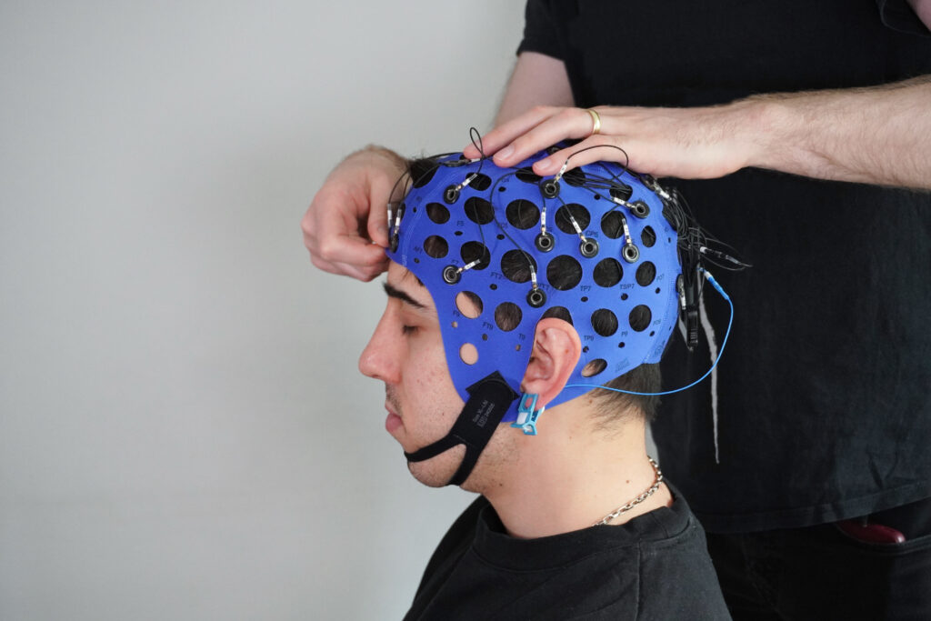
Figure 2a (Initial Placement): Gently seating the cap and clearing away hair from the forehead line.
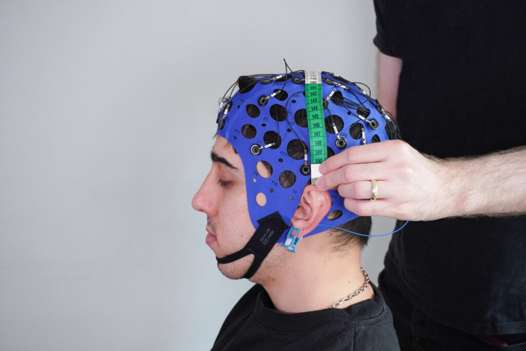
Figure 2b (Lateral Guide Check): Aligning the green vertical tracking tape up from the upper tip of the ear — which serves as a practical reference equivalent to the standard preauricular point for hitting the 50% midline distance.
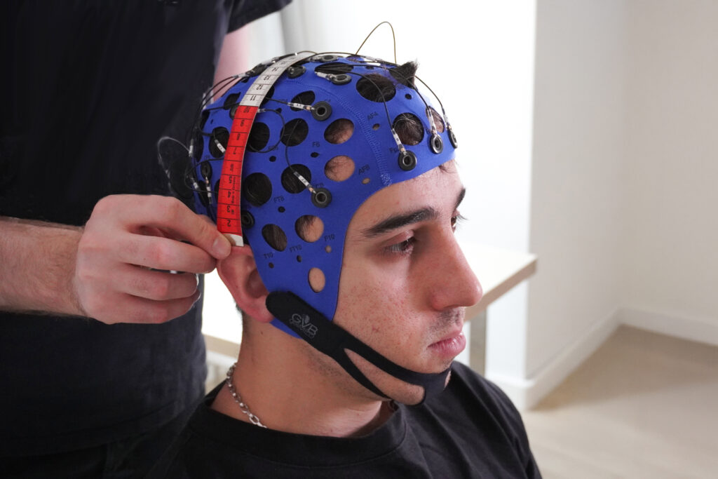
Figure 2c (Coronal Realignment): Verifying the vertical midline arc from ear to ear across the vertex.
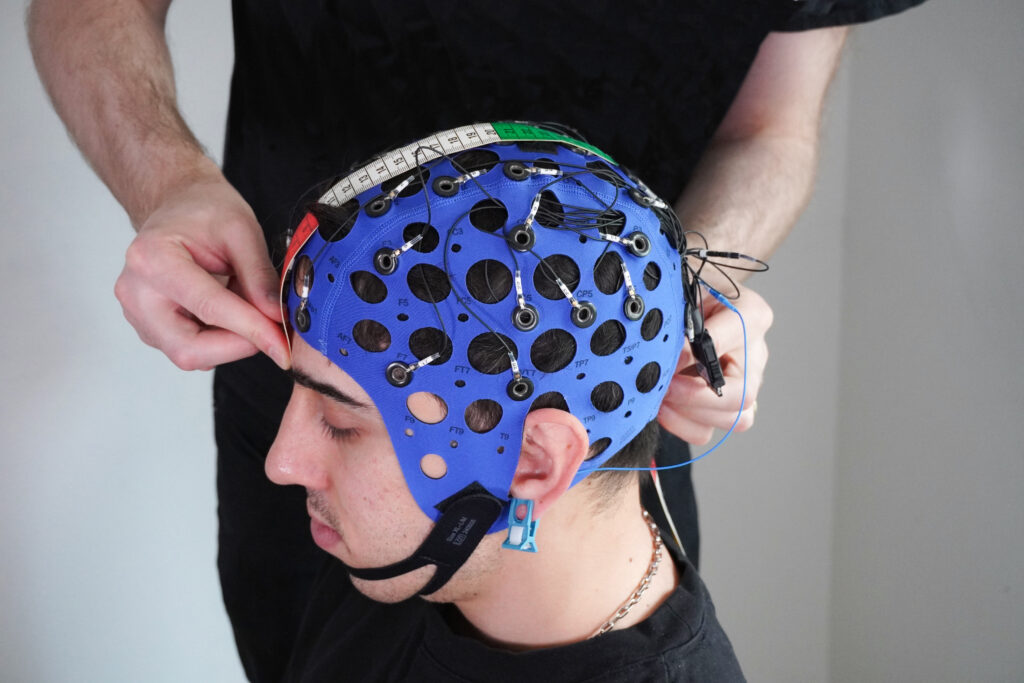
Figure 2d (Final Longitudinal Verification): Checking the complete sagittal scale placement across the top of the head to ensure perfect front-to-back symmetry.
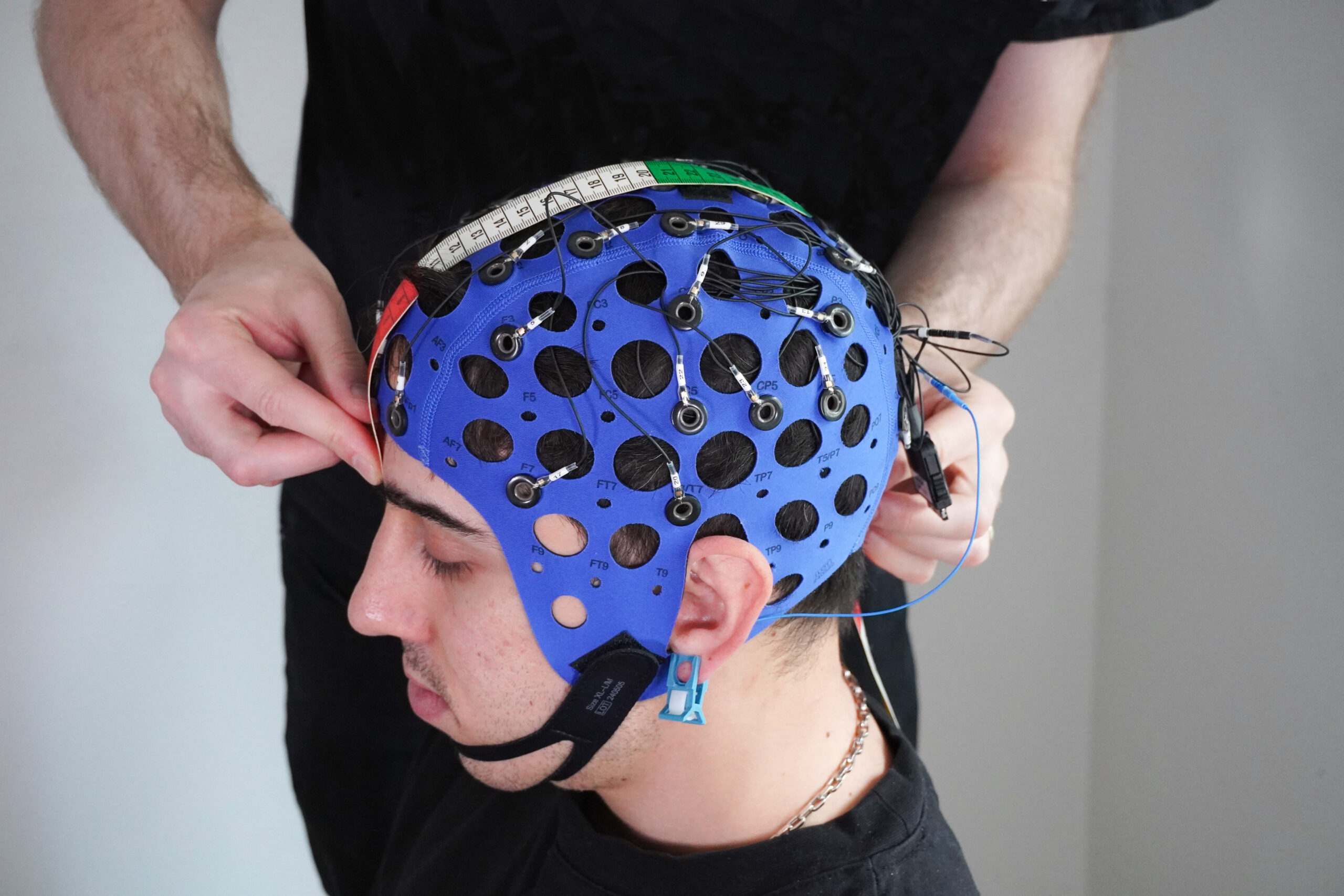
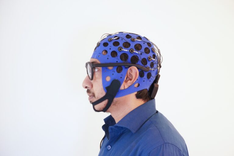
Step 3: Securing the Ear Reference & Module Integration
A pristine signal-to-noise ratio requires an electrically neutral reference point. Depending on your research objective, standard 10-20 practices offer several reference options. Using an ear clip electrode is one highly effective option. We simply clamp the specialized Mentalab ear clip onto the participant’s earlobe to target the standard A1/A2 positions.
Simultaneously, securely plug the electrode connector into the Mentalab Explore Pro data acquisition module (a click indicates the mechanical locking mechanism is engaged) and place the amplifier onto the hook-and-loop fastener on the back of the cap. Ensuring a firm connection minimizes cable sway and reduces motion artifacts during your recording session.
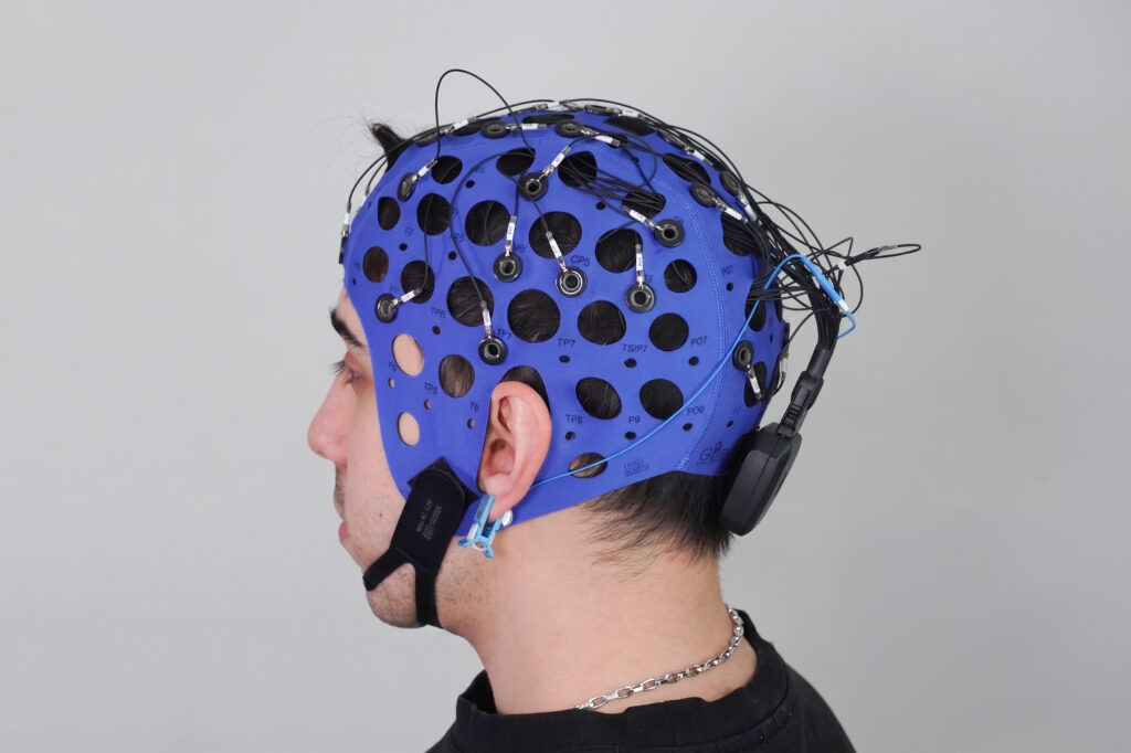
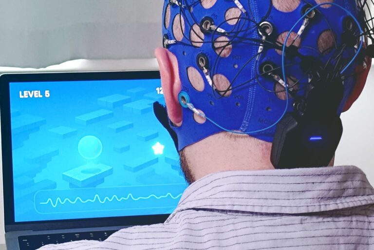
Figure 3: Close-up of the back of the cap, showcasing the locked amplifier connector module and the blue ear clip reference electrode.
Step 4: Final Overhead Inspection & Impedance Check
Once the amplifier is plugged in, look at the setup from a birds-eye view before injecting gel. The layout should look perfectly balanced, with the labels (Fz, Cz, Pz) running perfectly down the midline, flanked symmetrically by even numbers on the right hemisphere and odd numbers on the left hemisphere.
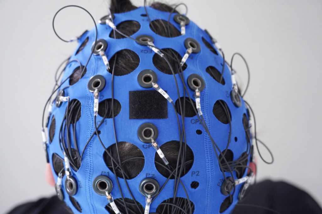
Figure 4: Overhead view confirming perfect bilateral symmetry of the electrode channels along the central coronal and sagittal intersecting lines.
You can now open your Mentalab software, connect to the amplifier, and check live impedances. Apply a small amount of gel to each electrode, starting with the reference electrode. If any channel shows high impedance, gently part the hair beneath that electrode socket using a blunt needle or applicator and apply a little more gel until the indicator turns green. You are now ready to record clean EEG data!
Selected References
- Jasper, H. H. (1958). The ten-twenty electrode system of the International Federation. Electroencephalography and Clinical Neurophysiology, 10, 371-375.
This was very useful. this is one of the best resources I found today. Please continue posting content like this.